In the face of pressing environmental challenges, cities around the world are seeking innovative solutions to create a sustainable and livable future. From energy efficiency to waste management, transportation to urban planning, a multitude of strategies are being implemented to reduce our carbon footprint and promote a greener urban environment. The Joint Research Centre has produced a collection of documents to help cities identify how to mitigate greenhouse gas emissions.
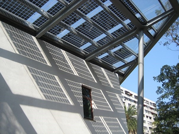
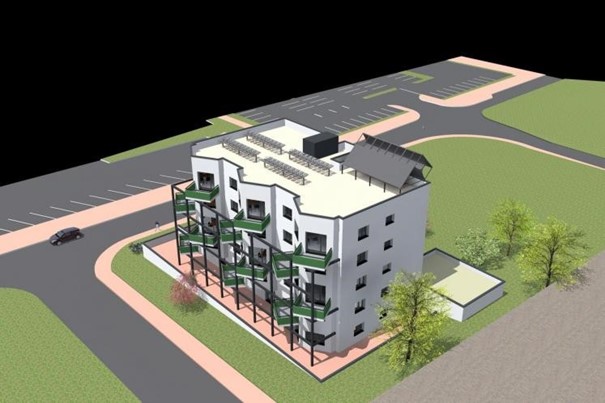
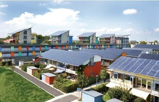
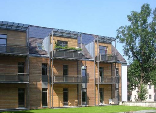
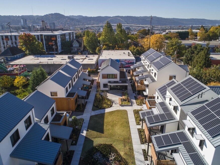
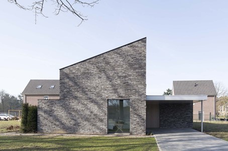
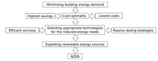
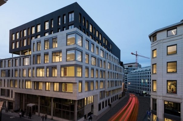
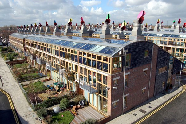
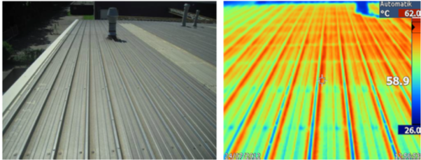
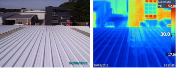
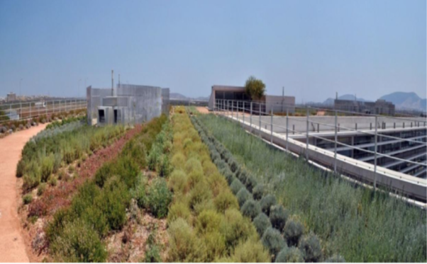
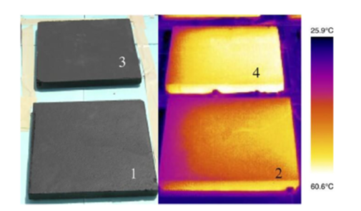
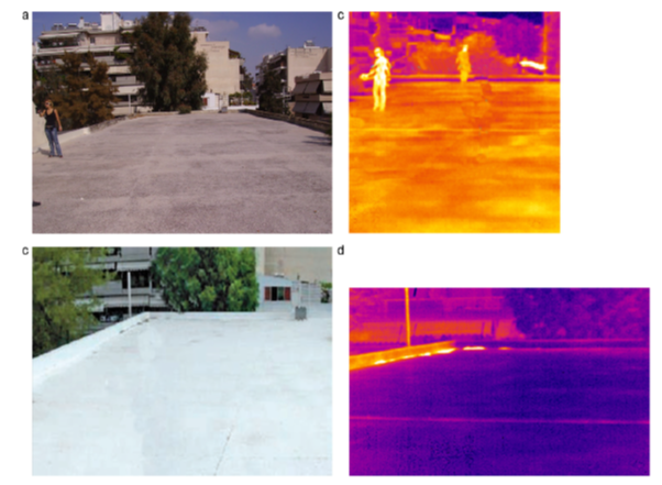
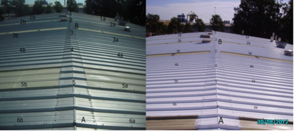
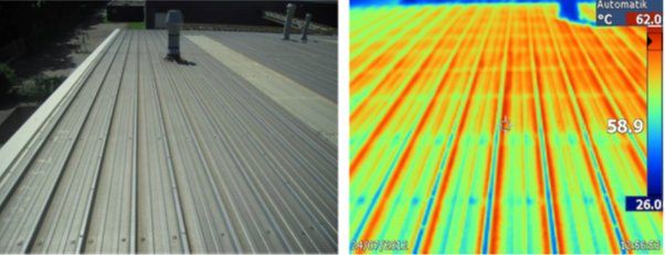
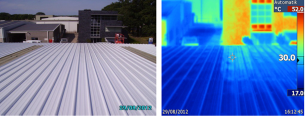
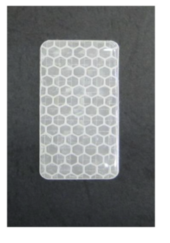
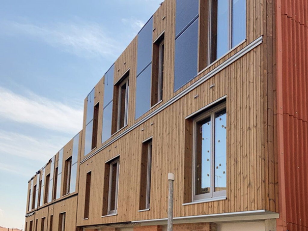
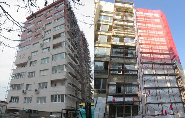
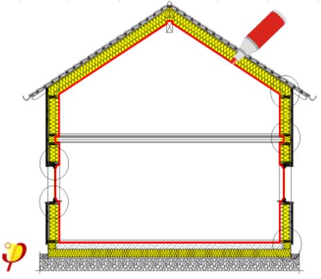
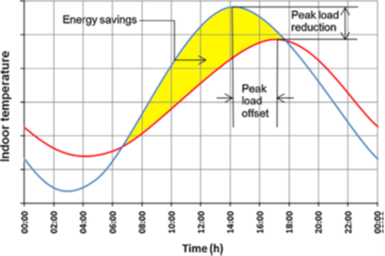
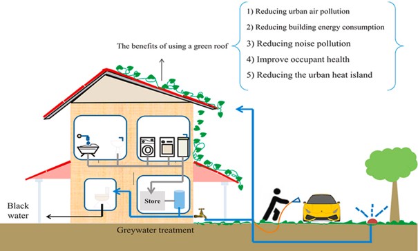
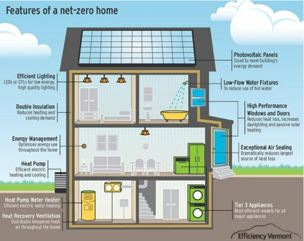
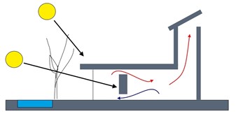
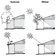
At the buildings, also known as the Stationary Energy sector, is necessary to reduce energy demand as much as possible. Currently, 75% of European houses are energy inefficient, which means that much of the energy needed is simply lost. There are several passive and active solutions to improve energy efficiency in buildings or deep energy renovation. Enhancing the thermal performance of building envelopes by improving the thermal properties of construction systems is possible by acting upon not just the insulation level, but also the thermal inertia through proper selection of the construction materials (Check more in Envelope thermal capacity). Green roofs can also be added, together with photovoltaics, introducing vegetation on/in man-made buildings and constructions to provide environmental, economic, and social benefits (i.e., clean air and water, climate regulation, food provision, erosion control, and places for recreation). To decrease the heat gains of buildings, reflective or cool materials can be applied on the roof or the facades of buildings (1-3). Reflective materials are characterized by high solar reflectance (SR) combined with a high thermal emittance value. Passive building design strategies, such as building orientation, passive heating and cooling can maintain comfortable indoor conditions with no need for energy, by taking advantage of location (climate), orientation, massing, shading, material selection, thermal mass, insulation, internal layout and the positioning of openings to allow the penetration of solar radiation, daylight, and ventilation in the desired amounts. Thanks to reducing energy needs, Nearly Zero Energy Buildings (NZEBs) can be achieved.
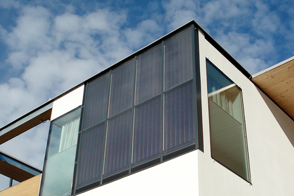
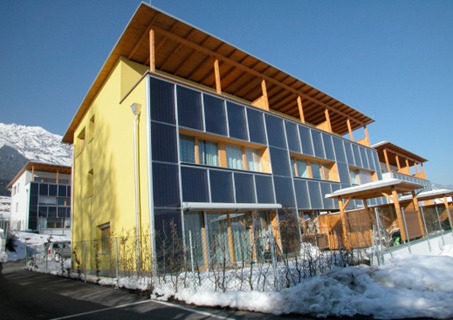
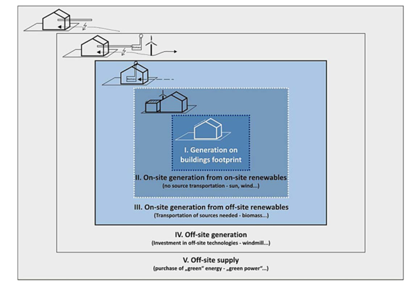
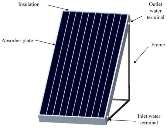
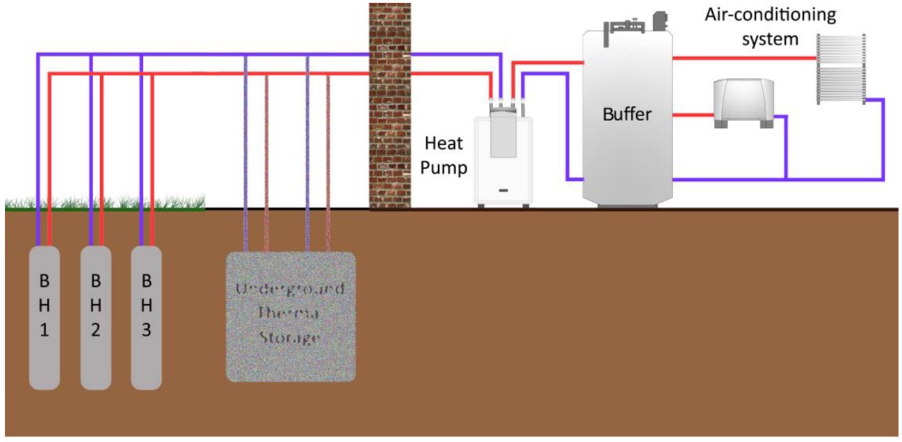
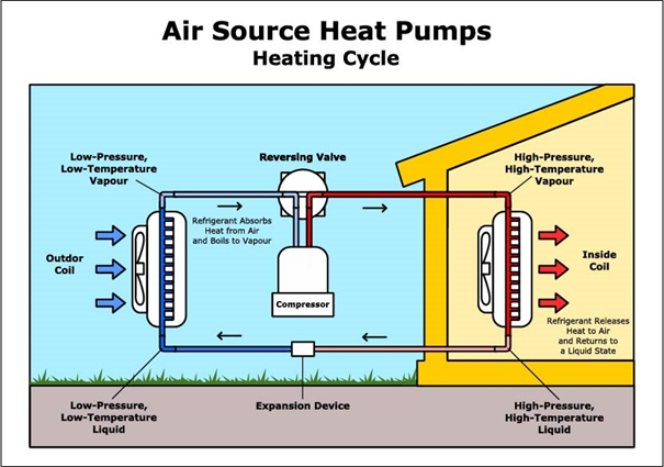
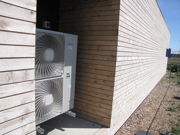
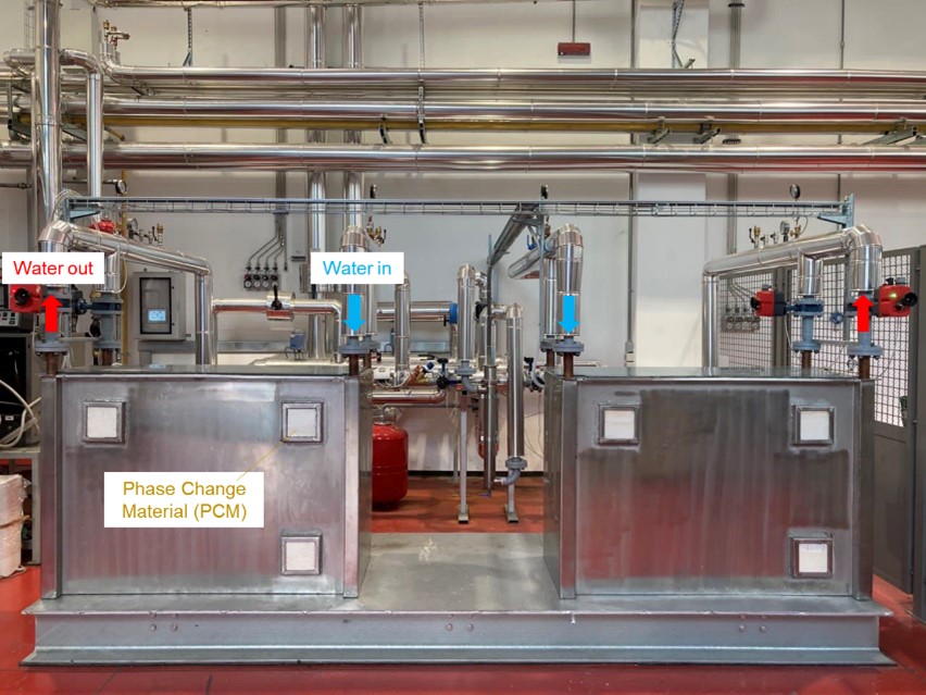
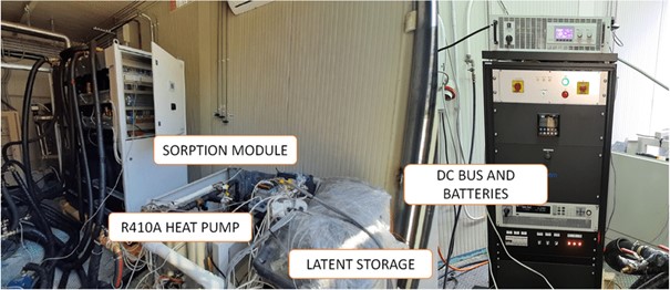
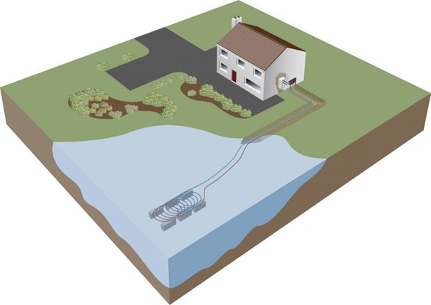
When everything possible has been done to reduce energy needs, renewable energy sources can be used such as Evacuated tubes solar collectors, Flat plate solar collectors, BIST (Building Integrated Solar Thermal), and many other thermal nearby renewable energy generation. Heat pumps are able to transfer heat from a lower-temperature heat source into a higher-temperature heat sink with low electricity consumption, such as air-source heat pump, ground-source heat pump and water-source heat pump. Thermal technologies can be integrated with different type of storage: sensible, latent, thermochemical, and PCM can also help with waste heat recovery. Seasonal storage can also be used.
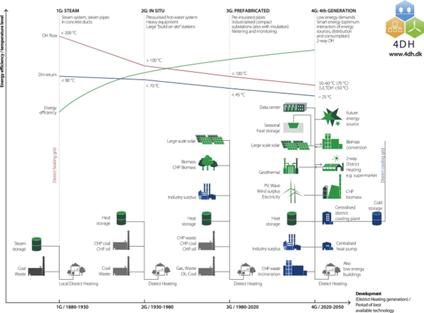
The decarbonisation of district heating networks is a major problem in cities. Renovating them (To make them more efficient), switching to sustainable fuels or renewable energy sources, or promoting the construction of new 3G to 5G District Heating and Cooling networks (energy generation to substations) in new areas, can help to descarbonise it. Technologies and applications for low/high temperature heat recovery in district heating are key for decarbonising existing networks, as DHN can use waste heat alongside renewable energy sources to heat up cities.
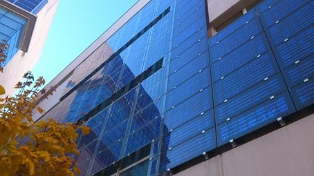
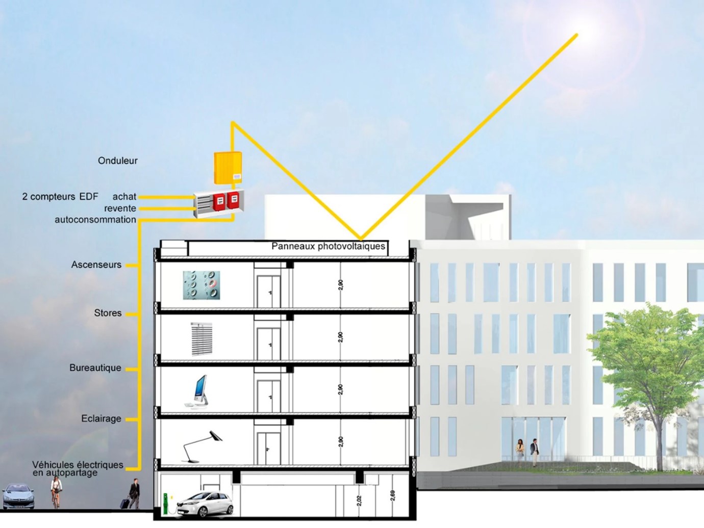
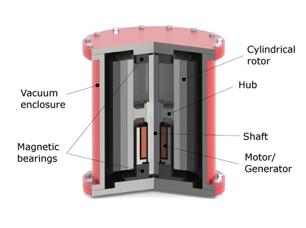
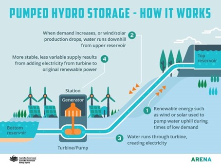
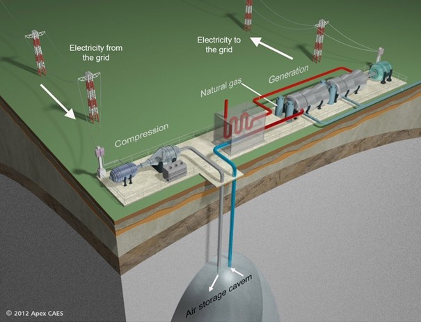
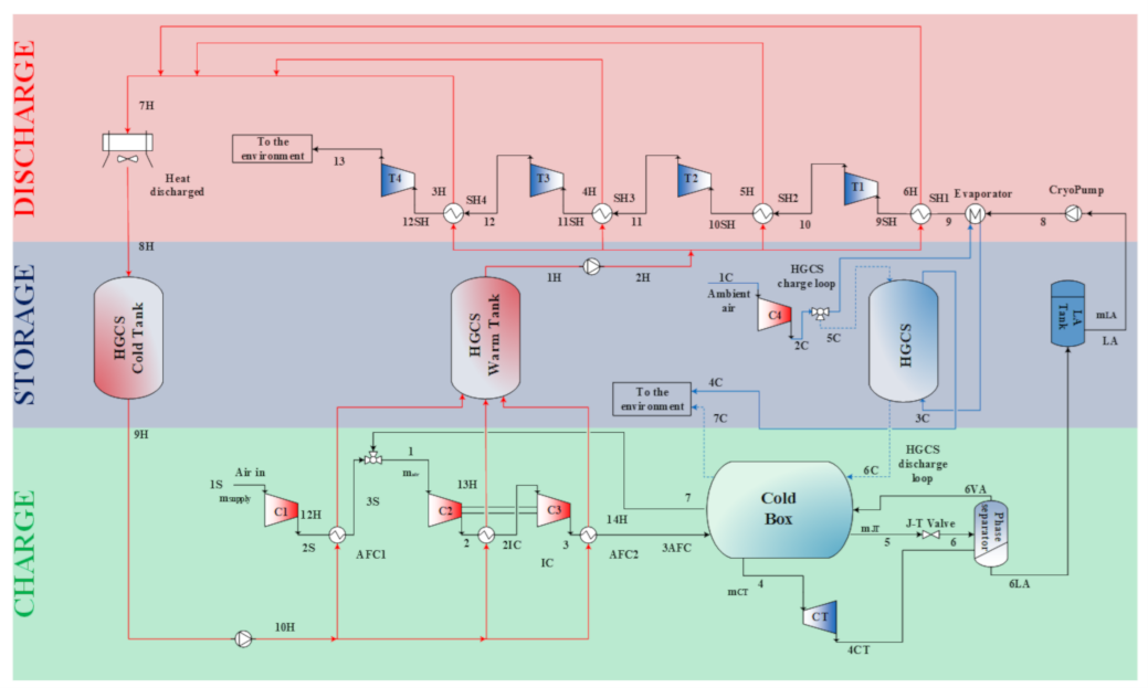
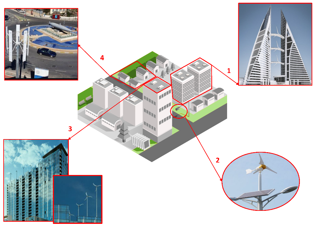
The use of renewable energy sources to produce electricity is one of the key actions of the energy transition for reducing carbon emissions to the atmosphere. On-site generation of electricity from renewables can help local municipalities, cities, and communities to have substantial environmental, economic, and social benefits, such as BIPV (Building Integrated Photovoltaics). Ocean contains a vast renewable energy potential, which could support sustainable long-term development and can be a crucial component in the world’s emerging blue economy. Ocean energy technologies are utilizing different resources such as tidal or waves. The production of electricity sometimes surpasses the demand, which can cause curtailment of RES. Thus, storage is needed such as Mechanical energy storage.
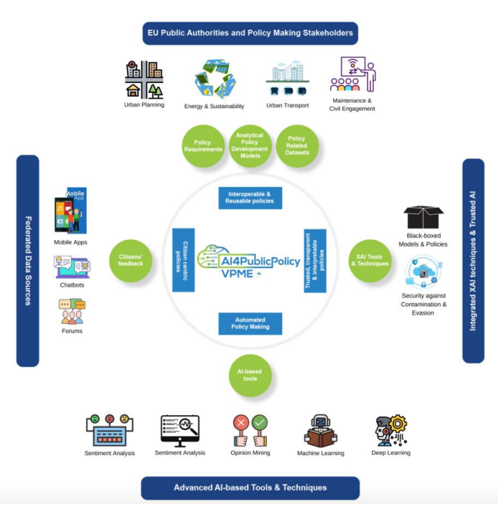
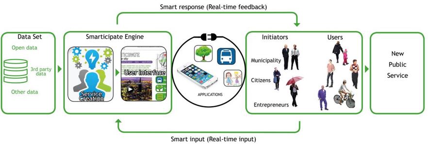
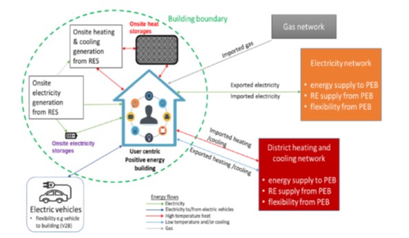
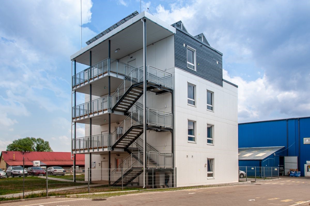
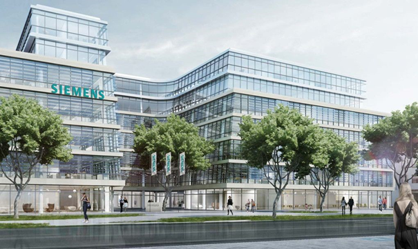
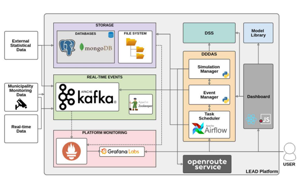
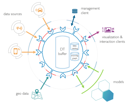
Integrating reduction of energy needs, renewable energy sources, storage, smart solutions,.- and sustainable mobility, Near Zero/ Positive Energy Districts (PEDs) or Positive Energy Buildings (PEBs) are achieved. To perform data analysis and optimize the performance of districts and cities, digital twins are used. Citizen participation platforms enables citizens to use digital technologies or platforms, e.g., combination of geographic information systems (GIS), Web 2.0 and mobile technologies (including video, mobile messaging and Internet access), for communication, engagement and deliberation on policy or planning challenges.
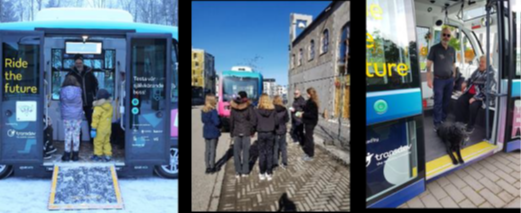
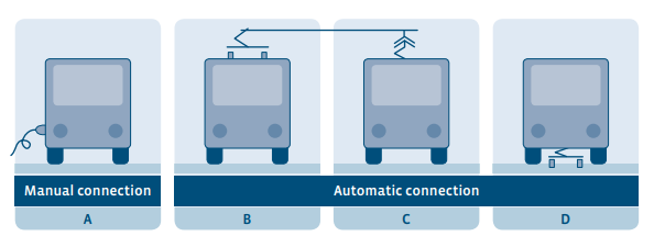
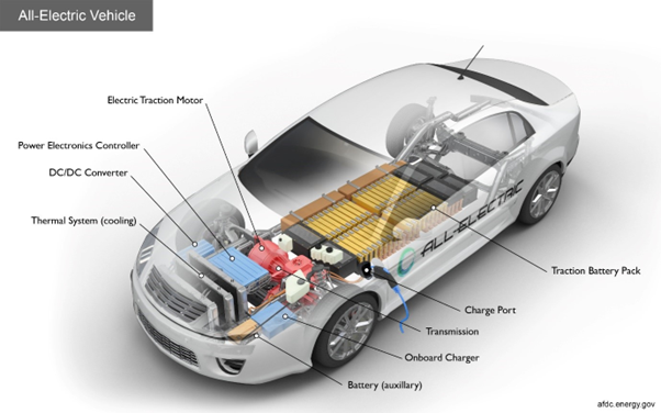
Transport and mobility is a key sector in city's Action Plans. For instance, buses are responsible for about 8% of the road transport Green House Gas emissions in EU. Buses with internal combustion engines are responsible also for emissions of fossil carbon dioxide (CO2) as well as air pollutants particulate matter (PM) or nitrogen oxides (NOx). Thus, zero emission buses, have a significant potential in the reduction of transport-related emissions in urban areas. Furthermore, to reduce road transport emissions, It has been increasingly recognized that electric cars provide an opportunity to reduce them and greatly increase air quality. In urban transport, there are some vehicle categories that benefit the most with the use of hydrogen vehicles, it being mostly related to the need for long autonomy, or the need for fast refueling, as compared to the longer recharging times for battery-powered vehicles.
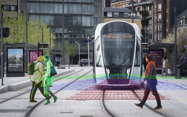
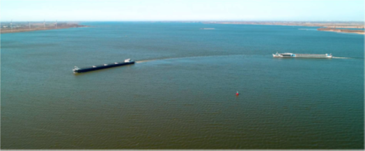
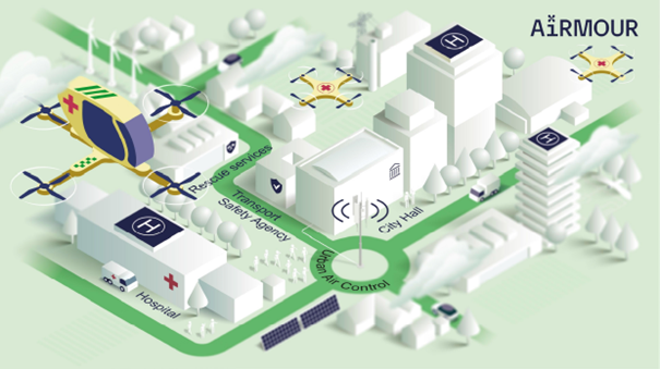
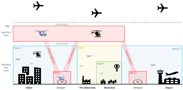
At Waterborne transport emissions are on the rise, and they represent today almost 3% of global GHG emissions. Ships entering EU ports emit 13% of the total EU transport GHG emissions, while inland waterway transport in the EU is estimated to emit 3.8 million tonnes of CO2 emissions per year. Apart from GHG emissions, shipping is responsible for water degradation, air pollution and noise pollution. All these impacts have a negative impact on cities and their inhabitants. Urban rail transit (e.g. light rail, rapid transit, commuter rail, metro rail) is an important component of urban mobility and transport. With relatively low lifecycle emissions, electrified rail transport is considered to be key for the reduction of emissions in transport in general, and also in urban areas. Lastly, drones, automated aircrafts or urban air mobility (UAM) concept, to transport goods and people in urban and suburban areas can achieve sustainable flights with no emissions during operation.
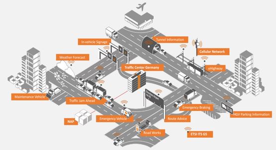
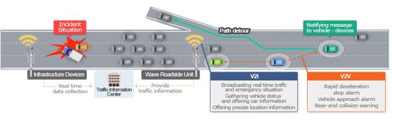
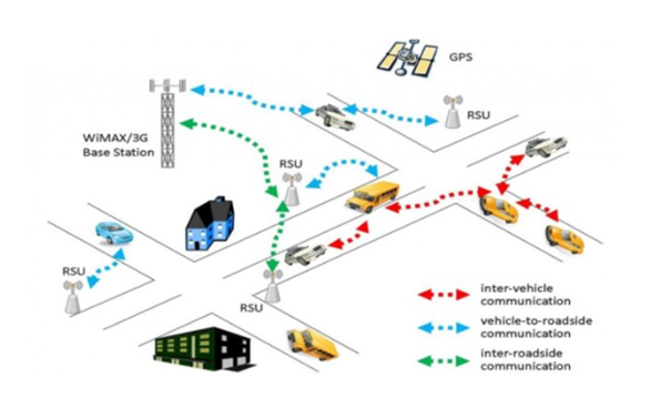
For making public transport more efficient, user-centered, inclusive and shared mobility concepts, for people and goods, that are based on automation and connectivity, such as Connected, Cooperative and Automated Mobility (CCAM) are needed. These innovative mobility concepts aim to complement and integrate the EU transport system with the aim to make it safer, smarter and more sustainable. Intelligent Transport Systems (ITS) apply information and communication technologies such as journey planners, eCall (a system that automatically alerts emergency services in case of an accident), short-range communications for improving passenger safety and reducing road fatalities, and connected and automated mobility concepts for passenger and goods.
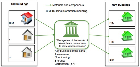
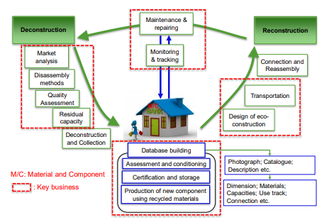
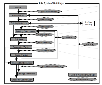
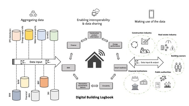
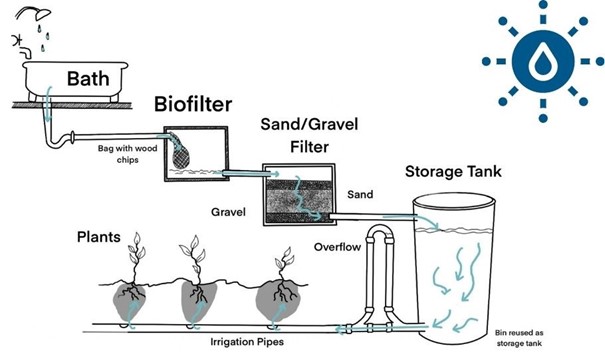
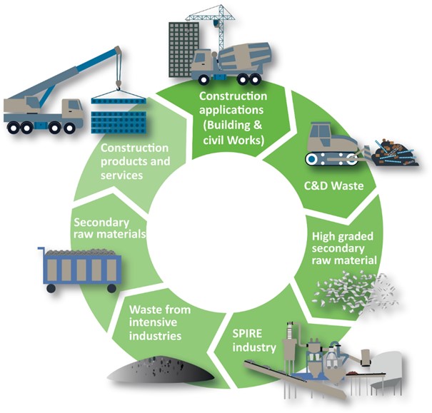
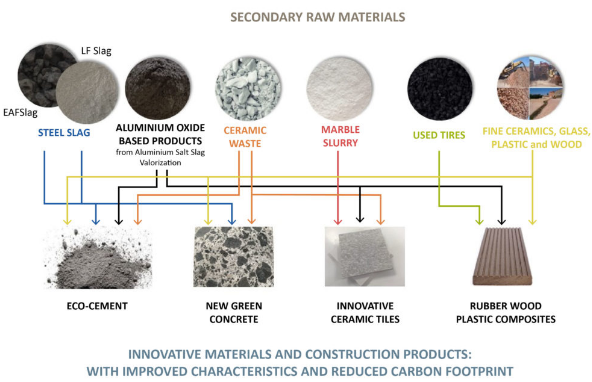
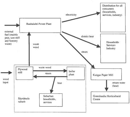
Currently, the construction sector is mostly following linear economy principles – consuming non-renewable virgin materials, producing landfill waste, and producing an overall negative environmental impact. Promoting local waste material banks or online registration of building and products can reduce emissions. Furthermore, the direct CO2 emissions related to concrete largely come from cement production, which can be reduced with several solutions for achieving low-carbon sustainable concrete. A residual value calculator can be used to provide insights into the residual financial value of building products, such as the interior and exterior facades of homes and offices. Also, at the building level, greywater can be reused and clean with greywater-nature-based solutions to reduce the amount of water demanded from the tap and the stress of water treatment plants. A digital building logbook is a common repository for all relevant building data that allows a variety of data, information and documents to be recorded, accessed, enriched and organised under specific categories [2]. The purpose of this novel concept is to ensure all relevant data is stored and made available to various stakeholders to support their decision-making process. Local or wider co-operation in industrial symbiosis can reduce the need for virgin raw material and waste generation
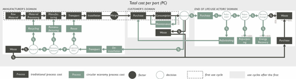
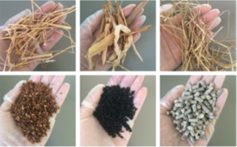
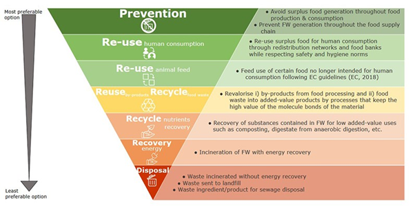
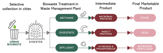
To maximize the recovery and valorization potential of existing materials in buildings and minimize waste in construction, optimal waste management at the end of life of buildings is essential. Several solutions exist to recycle food and nutrients, such as using waste products and leftovers from food production to create new products. Other circular economy strategies include, circular design of textiles which involves designing textiles in ways that make them last longer, create less waste during their entire life-cycle, are made from non-toxic material, and can be recycled. Product labels for circularity can encourage consumers to make more environmentally friendly purchasing choices, thus nudging manufacturers towards a more sustainable production; help extend product lifespan by promoting repair over disposal; and ensure correct sorting and recycling of end-of-life products. The Circular Life Cycle Cost (C-LCC) models can be use to evaluate the different options for components of ‘circular’ buildings, for instance, 1) the structure is made from reclaimed materials, 2) the structure is made from modules that can be changed, updated or reused, and 3) the structure is made from bio-based and biodegradable material.
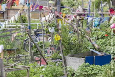
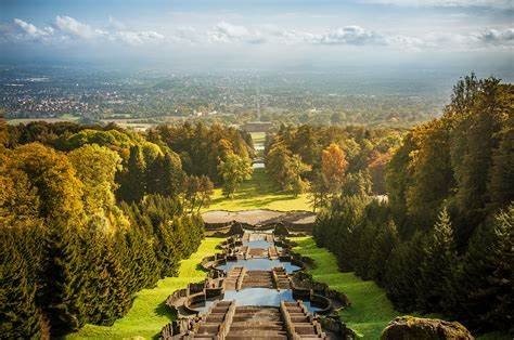
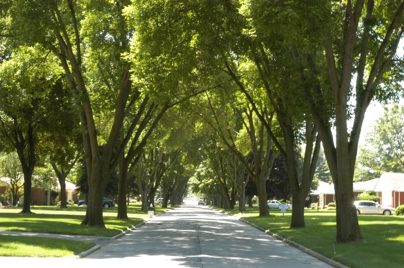
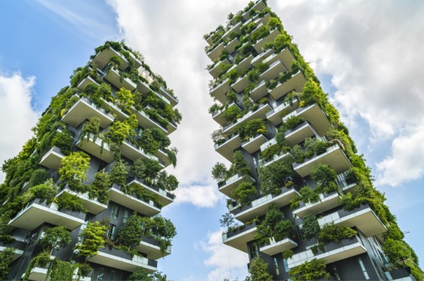
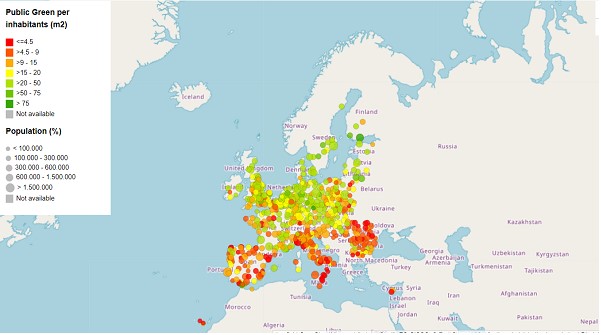
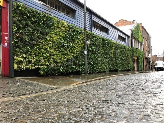
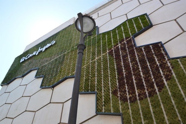
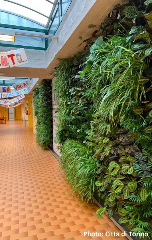
When residual emissions cannot be longer mitigated, natural carbon sinks can be used, such as Vertical green infrastructure(VGI), floating gardens or tree planting. Green fences, green noise barriers, or vertical mobile gardens have great potential to support climate transition of compact urban areas. VGI does not compete for land use but is able to support microclimate regulation through cooling capacities, reduce noise pollution, recycle and upcycle rainwater and grey water, produce food or habitat for species, and generate pleasant green spaces, with a significant aesthetic value.
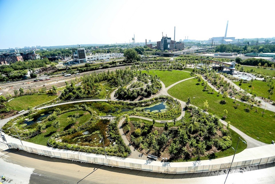
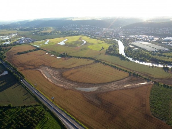
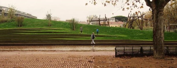
To make cities more resilient, several actions can be taken. Firstly, the establishment of floodable parks can help mitigate the impacts of flooding, which has become a critical natural hazard in Europe, causing substantial human and economic losses. By allowing parks to act as flood buffers, the intensity of flood events can be reduced, thereby safeguarding urban areas.
Another essential aspect is rainwater management and retention. As urbanization and industrialization have resulted in reduced vegetative cover and decreased water storage in the subsurface, surface runoff has become concentrated, leading to strain on sewage systems. By adopting strategies that mimic the natural water cycle, cities can effectively manage rainwater and promote its retention, alleviating the strain on infrastructure and reducing the risk of flooding.
Sustainable Urban Drainage Systems (SuDS) offer a diverse range of interventions to align modern drainage systems with natural water processes. By integrating sustainable practices, such as permeable pavements, green roofs, and constructed wetlands, cities can enhance their resilience against rainfall events, mitigate the risk of surface runoff, and preserve water resources.
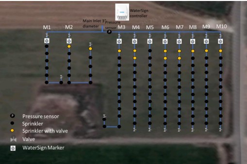
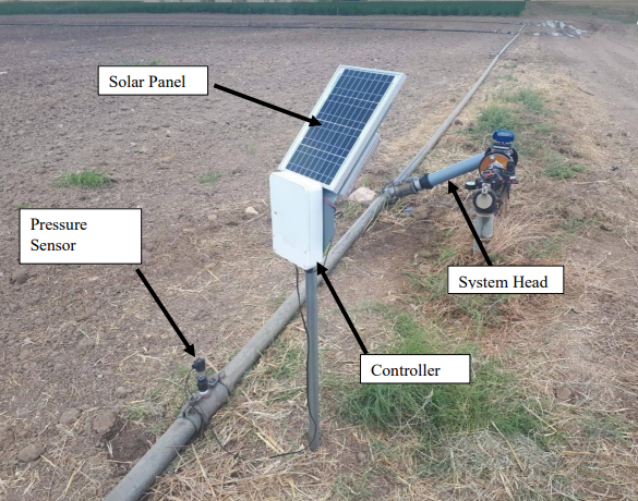
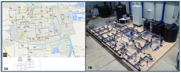
Detecting water leaks is another crucial aspect of ensuring water sustainability. Water scarcity is not only a consequence of climate change and rising demand but also due to unaccounted losses within water distribution networks. By implementing advanced leak detection technologies and efficient monitoring systems, cities can minimize water losses, optimize resource allocation, and enhance overall water management.
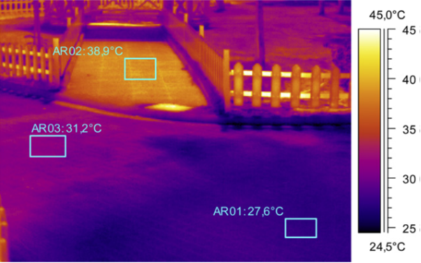
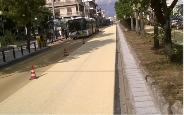
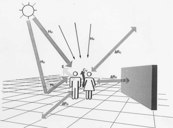
The urban heat island effect poses a significant challenge in cities, leading to increased energy demands for cooling and diminished comfort conditions. To mitigate this impact, various strategies can be employed. Greenery, such as urban forests, parks, and green roofs, can effectively counterbalance the heat island phenomenon by providing shade, reducing ambient temperatures, and improving air quality.
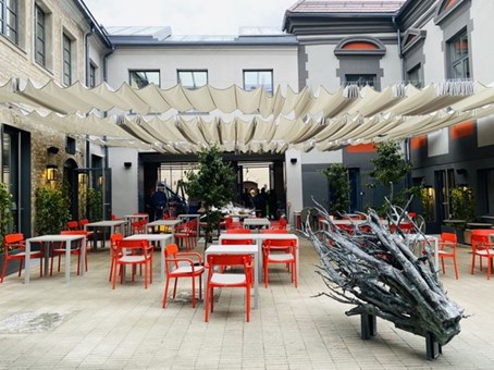
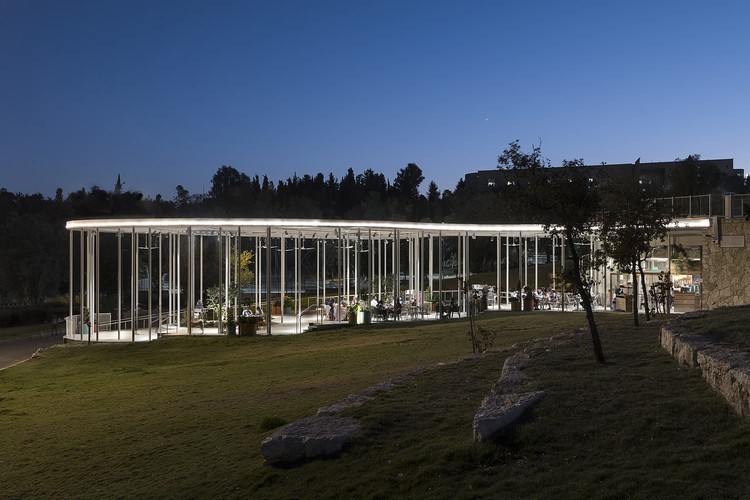
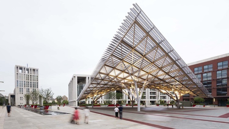
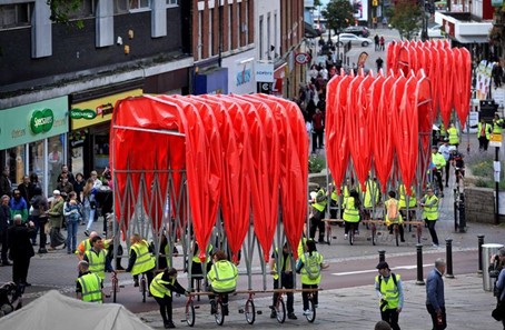
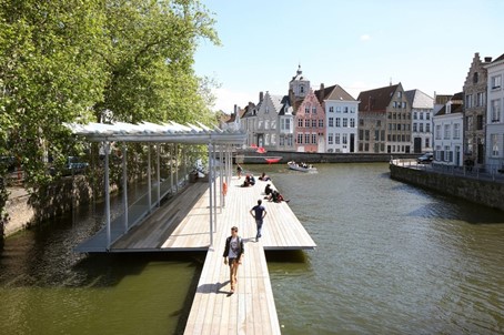
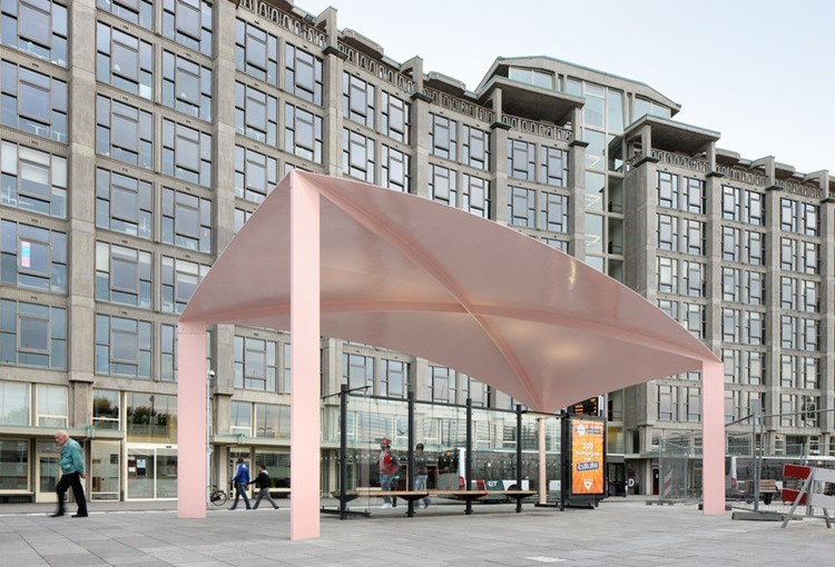
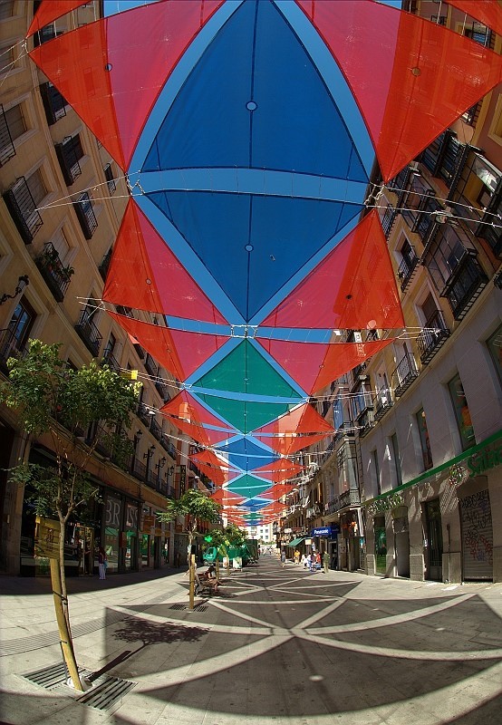
Shadings play a crucial role in mitigating the urban heat island effect by improving thermal protection of buildings and dissipating the building's thermal load to lower temperature heat sinks. By implementing shading techniques such as architectural design modifications, intelligent use of vegetation, and the strategic placement of sunshades, cities can significantly reduce the heat absorption of buildings, resulting in more comfortable living environments.
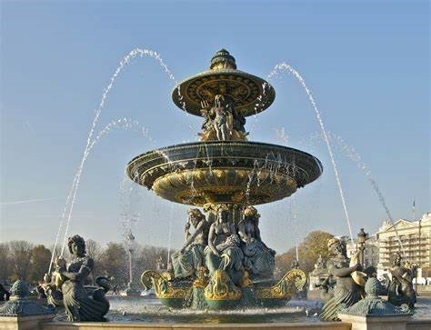
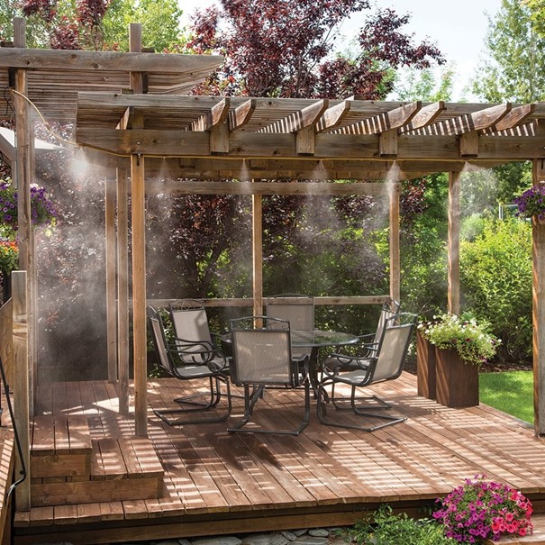
Evaporative cooling also offers a promising solution for combating the urban heat island effect. By employing techniques like misting systems, evaporative cooling towers, and water features, cities can effectively reduce temperatures, enhance thermal comfort, and decrease energy consumption for cooling purposes.
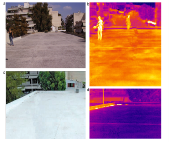
Additionally, cool urban surfaces (reflective) provide an innovative approach to counteracting the heat island phenomenon. By utilizing reflective materials on pavements, roofs, and other surfaces, cities can minimize heat absorption and radiation, thus reducing ambient temperatures and mitigating the energy demand for cooling.
Integrating these strategies and adopting a holistic approach to urban planning and development can enhance the resilience of cities, promote sustainability, and contribute to global efforts in combating climate change. By embracing natural carbon sinks, implementing green infrastructure, and prioritizing sustainable water and heat management practices, cities can create more livable and environmentally friendly spaces for their residents.
List of solutions:
|
THEMATIC AREA / Category
|
|
SOLUTION
|
Link
|
|
STATIONARY ENERGY
|
STATIONARY ENERGY SOLUTIONS
|
|
|
|
Building envelope solutions
|
Envelope insulation
|
https://netzerocities.app/resource-154
|
|
|
Envelope thermal capacity
|
https://netzerocities.app/resource-3507
|
|
|
Green roofs
|
https://netzerocities.app/resource-164
|
|
|
Cool roofs/facades and reflective (incl. retroreflective) roof/facades
|
https://netzerocities.app/resource-3477
|
|
RES and energy-harvesting solutions
|
PV panels
|
https://netzerocities.app/resource-388
|
|
|
Solar thermal panels
|
https://netzerocities.app/resource-438
|
|
|
Flat plate collectors (FPC)
|
https://netzerocities.app/resource-3517
|
|
|
Evacuated tube collectors (ETC)
|
https://netzerocities.app/resource-458
|
| |
BIPV (Building Integrated Photovoltaics) |
netzerocities.app/resource-3718 |
|
|
BIST (Building Integrated Solar Thermal)
|
https://netzerocities.app/resource-edit-3457
|
|
|
On-site and nearby renewable energy generation (electricity)
|
https://netzerocities.app/resource-3607
|
|
|
On-site and nearby renewable energy generation (heat/cold)
|
https://netzerocities.app/resource-3617
|
|
Heat recovery solutions
|
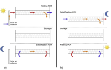
Heat captured during phase change (phase change materials) - Focus: waste heat recovery and free-cooling/free-heating using PCM
|
https://netzerocities.app/resource-edit-3537
|
|
Energy storage
|
Local heat/cold storage 1: sensible (hot water tanks and UTES (non-seasonal), pebble beds and Canadian storage), incl. heating and cooling applications
|
https://netzerocities.app/resource-3728
|
|
|
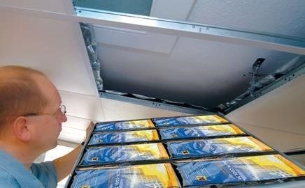
Local heat/cold storage 2: latent (PCM in HVAC) incl. heating and cooling applications
|
https://netzerocities.app/resource-828
|
|
|
Local heat/cold storage 3: thermochemical (absorption and adsorption) incl. heating and cooling applications
|
https://netzerocities.app/resource-3637
|
|
Passive building solutions
|
Passive building design strategies (building shape, plan, orientation, shading system)
|
https://netzerocities.app/resource-194
|
|
Sustainable and energy-efficient active solutions
|
Heat pumps: air source
|
https://netzerocities.app/resource-3447
|
|
|
Heat pumps: ground source
|
https://netzerocities.app/resource-3527
|
|
|
Heat pumps: water source
|
https://netzerocities.app/resource-3697
|
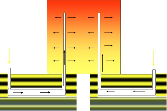
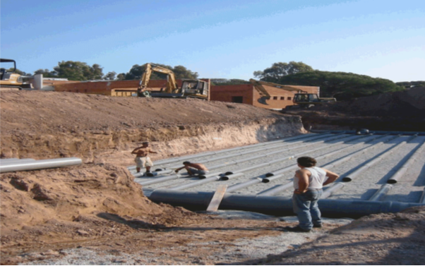
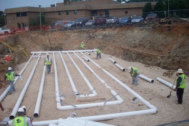
| |
Earth-air heat exchange technologies (EAHX) |
https://netzerocities.app/resource-3753 |
|
Low-carbon and sustainable building materials
|
Low-carbon sustainable concrete
|
https://netzerocities.app/resource-3567
|
|
Energy conservation
|
Urban heat island effect mitigation - Greening
|
https://netzerocities.app/resource-3667
|
|
|
Urban heat island effect mitigation - Cool urban surfaces (reflective)
|
https://netzerocities.app/resource-3384
|
|
|
Urban heat island effect mitigation - Evaporative cooling
|
https://netzerocities.app/resource-3708
|
|
|
Urban heat island effect mitigation - Shadings
|
https://netzerocities.app/resource-3677
|
|
Integrated solutions
|
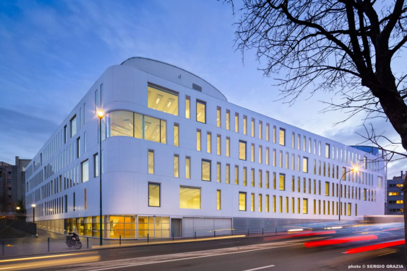
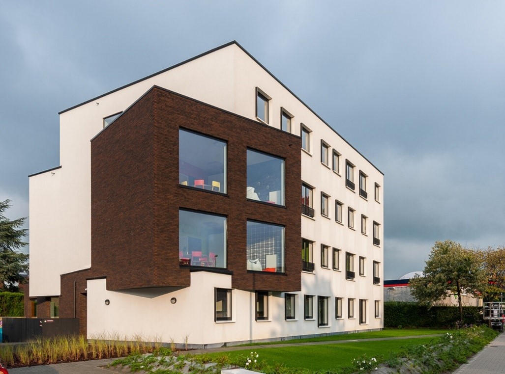
Positive Energy Buildings/Houses
|
https://netzerocities.app/resource-3374
|
|
|
Nearly Zero Energy Buildings (NZEBs)
|
https://netzerocities.app/resource-3364
|
|
|
Energy renovation/retrofit of existing buildings (below NZEB level)
|
https://netzerocities.app/resource-3497
|
|
|
Nearly Zero / Positive Energy Districts
|
https://netzerocities.app/resource-3354
|
|
|
|
|
|
|
DIGITAL
|
DIGITAL SOLUTIONS
|
|
|
|
Analytics and modelling solutions
|
Digital Twin
|
https://netzerocities.app/resource-1965
|
|
|
Digital building logbook
|
https://netzerocities.app/resource-3487
|
|
E-governance solutions
|
(Citizen) Participation Platforms
|
https://netzerocities.app/resource-2139
|
|
|
|
|
|
MOBILITY AND TRANSPORT
|
MOBILITY AND TRANSPORT SOLUTIONS
|
|
|
Vehicle solutions
|
Zero emission buses (electric and fuel cell)
|
https://netzerocities.app/resource-398
|
|
|
Zero emission electric cars
|
https://netzerocities.app/resource-408
|
|
|
Zero emission vessels
|
https://netzerocities.app/resource-3437
|
|
|
Urban Air Mobility
|
https://netzerocities.app/resource-3407
|
|
|
Urban and underground rail
|
https://netzerocities.app/resource-3417
|
|
|
Automation
|
https://netzerocities.app/resource-418
|
|
Infrastructure solutions
|
Bi-directional EV charging
|
https://netzerocities.app/resource-428
|
|
|
Public charging infrastructure for EVs
|
https://netzerocities.app/resource-448
|
|
|
Intelligent transport systems infrastructure
|
https://netzerocities.app/resource-498
|
|
|
Hydrogen Fuel Cell vehicles (incl. infrastructure, refuelling stations)
|
https://netzerocities.app/resource-508
|
|
|
|
|
|
SUSTAINABLE RESOURCE MANAGEMENT & CIRCULAR ECONOMY
|
SUSTAINABLE RESOURCE MANAGEMENT & CIRCULAR ECONOMY SOLUTIONS
|
|
Circular textiles
|
Textile and fashion design for circularity
|
https://netzerocities.app/resource-2301
|
|
Construction and Buildings
|
Optimal management of waste at the end of building life cycle
|
https://netzerocities.app/resource-2467
|
|
|
Re-using local building waste (e.g. local waste material bank)
|
https://netzerocities.app/resource-2477
|
|
|
Residual Value Calculator for construction parts/material, consumer products
|
https://netzerocities.app/resource-2498
|
|
|
Online register with building and infrastructure material/parts/products for reuse/circular use
|
https://netzerocities.app/resource-2508
|
|
|
Circular Life Cycle Cost (C-LCC): ECO-tool (for deep renovation)
|
https://netzerocities.app/resource-2518
|
|
WATER: Building level
|
Grey water treatment (including NBS) and reuse
|
https://netzerocities.app/resource-2543
|
| |
Rain water retention e.g. on roofs |
https://netzerocities.app/resource-3587 |
| WATER: Urban water cycle |
Water leaks detection |
https://netzerocities.app/resource-3687 |
|
|
Rainwater management and retention
|
https://netzerocities.app/resource-3597
|
|
ENERGY: Energy Efficiency
|
Improvement of energy efficiency by active and passive solutions in buildings
|
https://netzerocities.app/resource-3557
|
|
|
Industrial symbiosis assessment and solution pathways for facilitating cross-sectoral energy and material exchange
|
https://netzerocities.app/resource-2564
|
|
ENERGY: Energy generation - RES
|
Guarantee the energy saving/production in buildings
|
https://netzerocities.app/resource-2594
|
|
FOOD
|
Food and nutrients recycling
|
https://netzerocities.app/resource-3467
|
|
CIRCULAR RETAIL SECTOR
|
Product labelling for circularity/durability/repairability
|
https://netzerocities.app/resource-3577
|
|
|
|
|
|
NATURE-BASED
|
NATURE-BASED SOLUTIONS
|
|
|
|
Urban carbon storage and sequestration
|
Vertical green infrastructure: Green fences, green noise barriers, vertical mobile gardens
|
https://netzerocities.app/resource-1188
|
|
|
Allotments, community gardens, floating garden
|
https://netzerocities.app/resource-1218
|
|
|
Tree planting (urban forestry/urban trees), parks and (semi) natural urban green areas
|
https://netzerocities.app/resource-1258
|
|
Water interventions
|
Floodable park
|
https://netzerocities.app/resource-1328
|
|
|
Sustainable Urban Drainage (SUD) systems
|
https://netzerocities.app/resource-1358
|
|
|
|
|
|
ENERGY GENERATION
|
ENERGY GENERATION SOLUTIONS
|
|
|
RES electricity and thermal energy generation
|
Solar thermal
|
https://netzerocities.app/resource-438
|
|
|
Photovoltaics
|
https://netzerocities.app/resource-388
|
|
|
Tide, wave and other ocean energy
|
https://netzerocities.app/resource-3657
|
|
Energy recovery
|
Technologies and applications for low/high temperature heat recovery in DH
|
https://netzerocities.app/resource-858
|
|
Energy and E-fuel storage
|
Mechanical storage
|
https://netzerocities.app/resource-3647
|
|
|
Seasonal storage (pits, UTES, sorption)
|
https://netzerocities.app/resource-848
|
|
Infrastructure
|
From 3G to 5G district heating and cooling networks (generation to substations)
|
https://netzerocities.app/resource-878
|
|
|
|
|


 []
[]


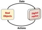 A digital twin presents a digital replica of a real object or process or a system and uses data from the real environment to represent, analyse, validate and simulate present and future behaviour
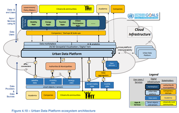


 '
'

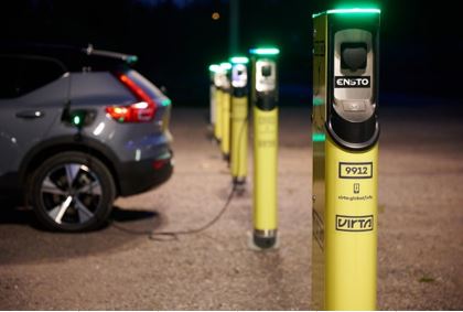
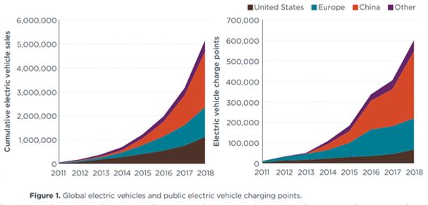
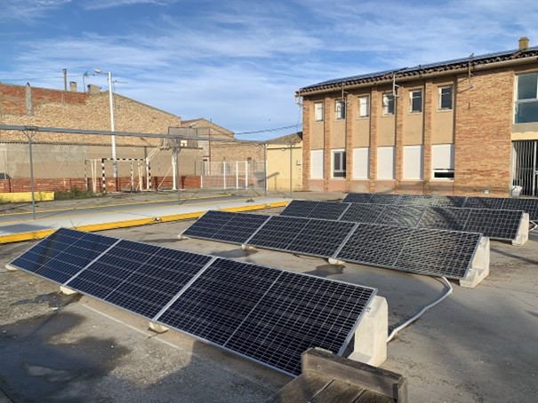
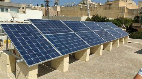
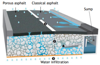

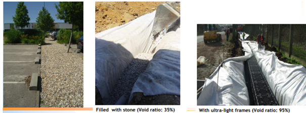
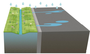
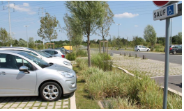
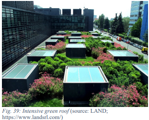
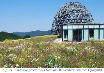
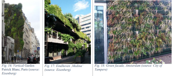
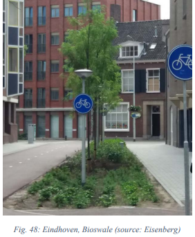
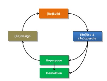
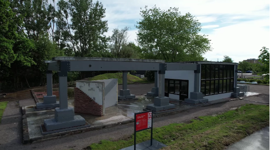
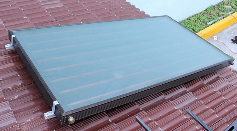
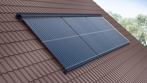
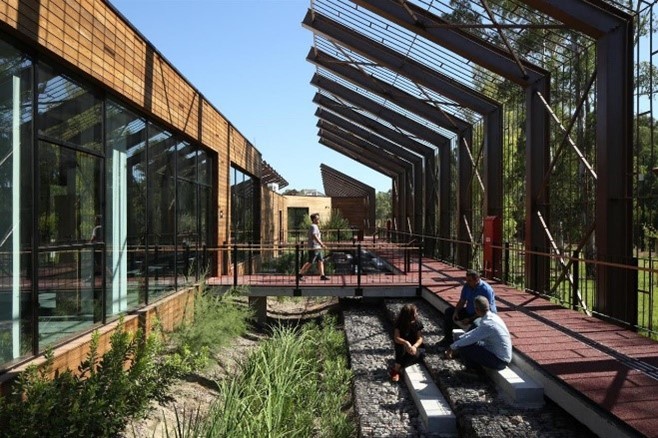
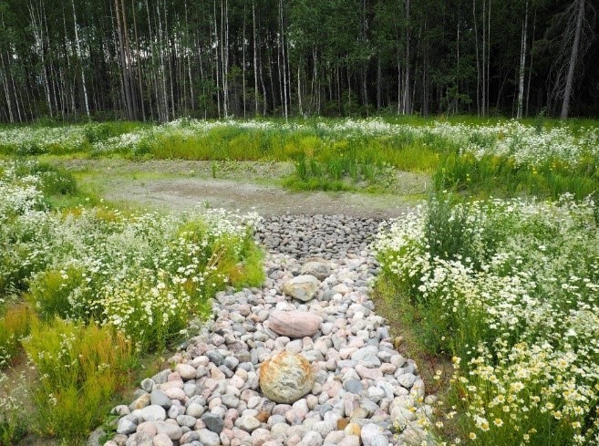
 Figure 3